Boolean Constants and Variables
Boolean values are binary only:
0or1.Boolean variables represent logic levels, not numeric quantities.
Logic levels correspond to voltage states in digital circuits.
Inputs are logic variables whose values determine output logic levels.
Boolean algebra is simpler than ordinary algebra:
- No fractions, negatives, roots, logarithms, etc.
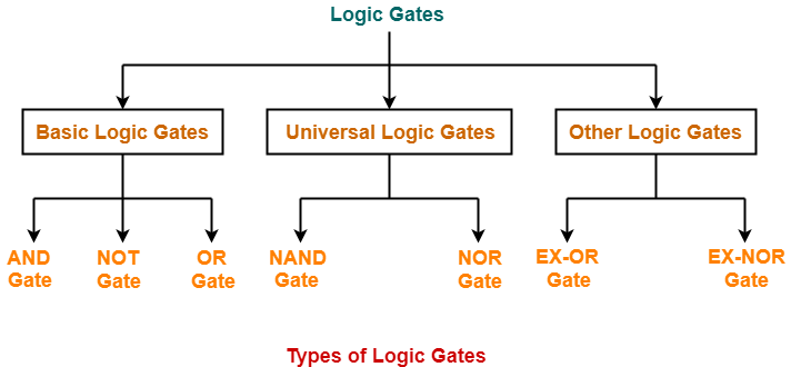
Three basic logic operations only:
- OR
- AND
- NOT
Logic operations are implemented using logic gates (built from electronic components).
Boolean algebra expresses input–output relationships of logic circuits.
Truth Tables
A truth table lists:
- All possible input logic combinations
- Corresponding output logic levels
Used to fully describe a logic circuit's behavior.
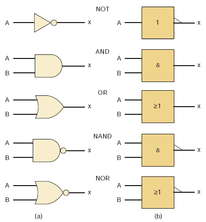
OR Operation (OR Gate - 7432)
Expression:
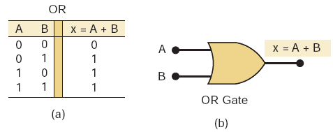
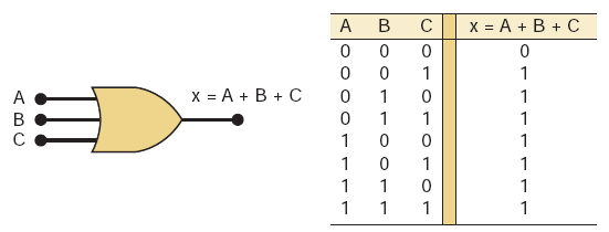
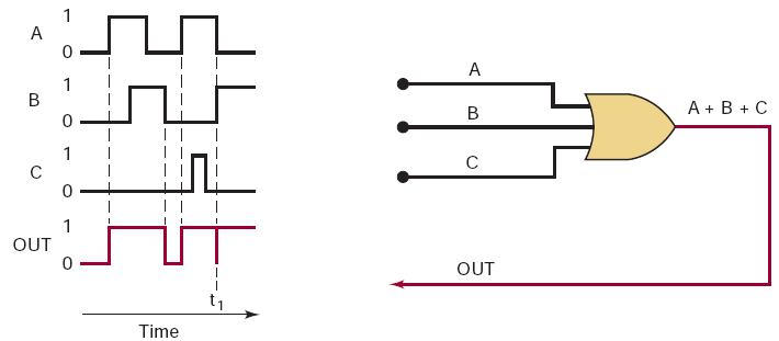
Output is
1if any input is 1.When inputs transition simultaneously:
- Inputs may briefly be in an undefined region
- Output may show a glitch (spike)
Glitch characteristics depend on input transition speed.
AND Operation (AND Gate - 7408)
Expression:
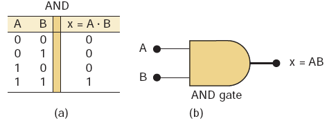
Output is
1only when both inputs are 1.Observations:
- If
B = 0->X = 0regardless ofA - If
B = 1->X = A
- If
AND gate can function as an inhibit/enable circuit:
B = 0-> inhibit (output forced to 0)B = 1-> enable (A passes to output)
NOT Operation (Inverter Gate - 7404)
Expressions:
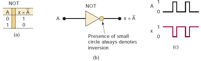
- Output is the complement of the input.
- Single-input logic operation.
NOR and NAND Gates
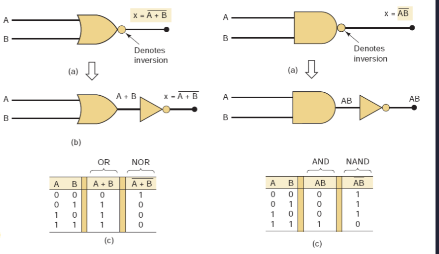
NOR Gate - 7402
Formula:
- Equivalent to OR + NOT.
- OR output HIGH -> NOR output LOW.
| A | B | |
|---|---|---|
| 0 | 0 | 1 |
| 0 | 1 | 0 |
| 1 | 0 | 0 |
| 1 | 1 | 0 |
- Output is HIGH only when all inputs are LOW.
NAND Gate - 7400
Formula:
- Equivalent to AND + NOT.
- AND output HIGH -> NAND output LOW.
| A | B | |
|---|---|---|
| 0 | 0 | 1 |
| 0 | 1 | 1 |
| 1 | 0 | 1 |
| 1 | 1 | 0 |
- Output is LOW only when all inputs are HIGH.
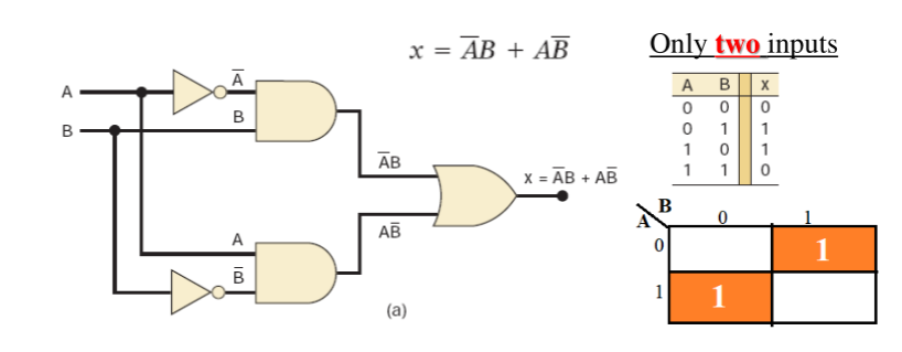
Exclusive-OR (XOR Gate - 7486) and Exclusive-NOR (XNOR Gate - 74266) Circuits
- Two special logic circuits frequently used in digital systems.
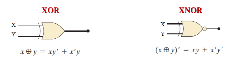
XOR Gate
| A | B | |
|---|---|---|
| 0 | 0 | 0 |
| 0 | 1 | 1 |
| 1 | 0 | 1 |
| 1 | 1 | 0 |
- Output is HIGH when the two inputs are different.
- XOR gates have only two inputs (no 3- or 4-input versions).
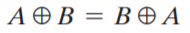
- XOR operation is:
- Commutative
- Associative
XOR Properties
- Commutative: order of inputs does not affect output.
- Associative: grouping of operations does not affect output.

Exclusive-NOR (XNOR) Gate
- Produces the complement of XOR output.
Formula:
| A | B | |
|---|---|---|
| 0 | 0 | 1 |
| 0 | 1 | 0 |
| 1 | 0 | 0 |
| 1 | 1 | 1 |
- Output is HIGH when inputs are at the same.
Algebraic Description of Logic Circuits
- Any logic circuit can be fully described using OR, AND, NOT.
- These three operations are the basic building blocks of digital systems.
Boolean Theorems (Rules)
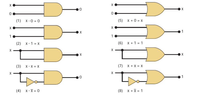
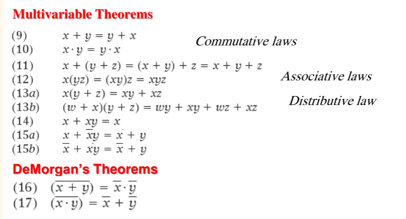
- Boolean expressions can be simplified using standard theorems.
- Used to reduce circuit complexity and gate count.
DeMorgan's Theorems
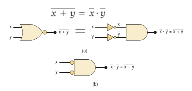
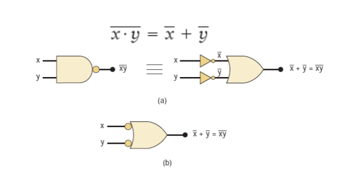
- Provide rules for complementing expressions.
- Convert:
- AND -> OR (with inverted inputs)
- OR -> AND (with inverted inputs)
Universality of NAND and NOR Gates
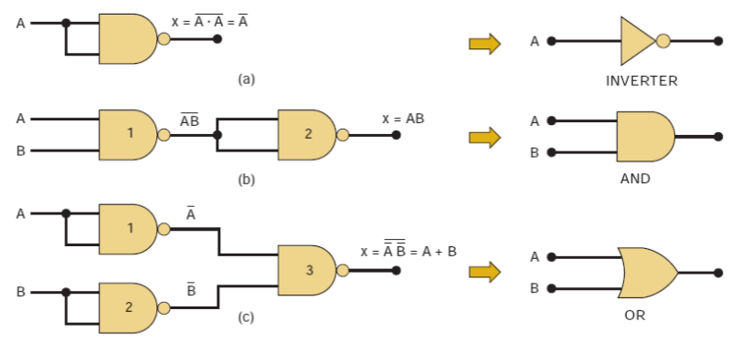
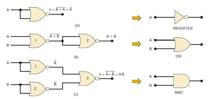
- NAND and NOR are universal gates.
- Any logic function (AND, OR, NOT) can be implemented using only NAND or only NOR gates.
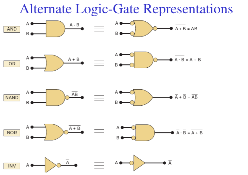
Alternative (Bubbled) Logic Gates
- Alternative / Alternate / Bubbled gates produce the same output as standard gates.
- Used when the original gate symbol is unavailable.
Deriving an Alternate Symbol
- Invert all inputs and outputs (add bubbles).
- Change AND <-> OR.
- Inverter: operation symbol does not change.
Active-HIGH and Active-LOW Signals
- No bubble on a line -> Active-HIGH
- Bubble present -> Active-LOW
- Bubbles define how a circuit's operation is interpreted.
Output Activity
- Action occurs at logic
1-> output is active-HIGH - Action occurs at logic
0-> output is active-LOW - If both states cause actions, either representation may be used.
Design Guideline
- Prefer bubble-to-bubble and non-bubble-to-non-bubble connections.
Asserted Levels
- Asserted = signal is in its active state
- Unasserted = signal is inactive
Labeling Logic Signals
Active-LOW Signals
- Indicated using an overbar
- No overbar -> active-HIGH
Bistate Signals
- Signal has two active meanings, one for HIGH and one for LOW.
Example: 
- HIGH -> Read (RD)
- LOW -> Write (WR)
IEEE/ANSI Standard Logic Symbols
- IEEE/ANSI Standard 91-1984 defines a newer set of logic symbols.
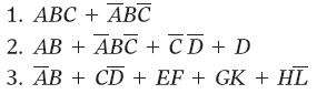
Sum-of-Products (SoP) Form
- Logic expression written as OR of product (AND) terms.
- Each product term contains variables in complemented or uncomplemented form.
- Required for some simplification and design methods.
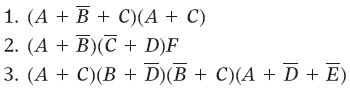
Product-of-Sums (PoS) Form
- Logic expression written as AND of sum (OR) terms.
- Each sum term contains variables in complemented or uncomplemented form.
Simplifying Logic Circuits
- Goal: reduce terms, variables, gates, and connections.
- Benefits:
- Lower cost
- Smaller size
- Improved reliability
Methods
- Algebraic simplification
- Karnaugh Map (K-map)
Standard Forms
- Product term: (XYZ) -> AND of literals
- Sum term: (X + Y + Z) -> OR of literals
In Boolean algebra:
- Product = AND
- Sum = OR
Minterms and Maxterms
- Minterm: output = 1 for one input combination, 0 for all others.
- Maxterm: output = 0 for one input combination, 1 for all others.
- Minterm and maxterm with the same subscript are complements.
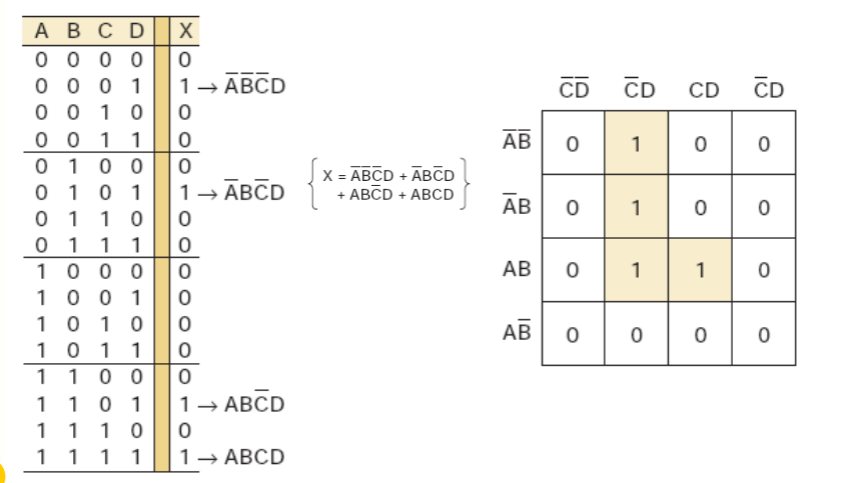
- Boolean functions can be written as a sum of minterms from the truth table.
Karnaugh Map (K-Map)
- Graphical method to simplify logic expressions or derive circuits from truth tables.
- Practical limit: 5–6 variables.
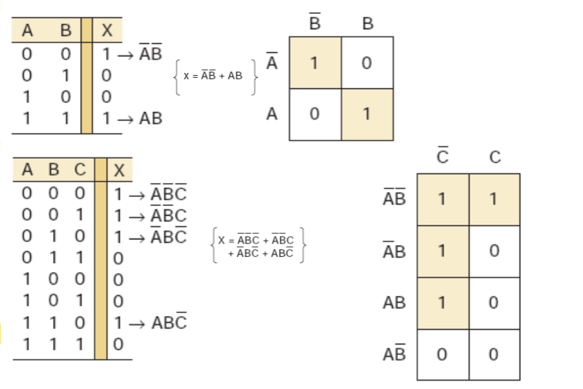
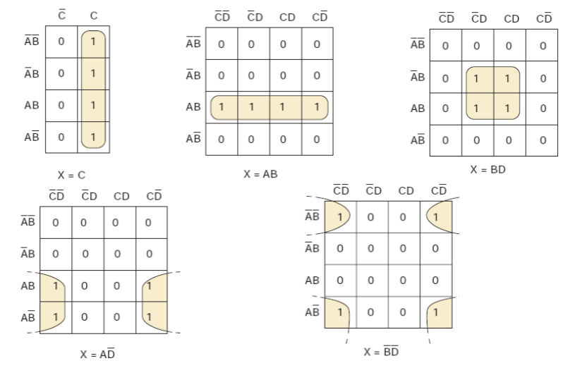
Looping in K-Maps
- Adjacent 1s are grouped to simplify expressions.
- Group sizes: pairs, quads, octets (2, 4, 8).
K-Map Simplification Steps
- Place 1s and 0s from the truth table.
- Loop isolated 1s.
- Loop pairs with single adjacency.
- Loop octets (8 squares) when possible.
- Loop quads (4 squares) using the fewest loops.
- Loop remaining pairs if needed.
- OR all terms generated by loops.
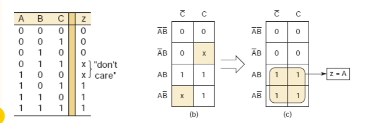
Don't-Care Conditions
- Input combinations that never occur or have unspecified outputs.
- Can be treated as 0 or 1 to achieve further simplification.