Lecture 3: Entity Relationship Diagram (ERD)
Database Model
A database can be represented as:
- A collection of entities.
- Relationships among those entities.
The Entity Relationship (ER) diagram serves as a blueprint for database design.
The ER model provides a graphical view of the logical data structure.
Entity Relationship Diagram (ERD)
ERD is a graphical tool used for:
- Modeling data.
- Designing logical database structures.
- Understanding the relationships between entities.
Identifies concepts (entities) and the relationships between them.
Purposes of an ERD
- Provides a clear understanding of the data to be stored.
- Serves as documentation for the database design.
- Helps communicate the logical structure to end-users and developers.
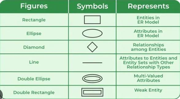
Components of an ERD
- Entity – An object or concept about which data is stored.
- Relationship – An association between entities.
- Cardinality – Specifies the number of entity instances involved in a relationship.
- Attribute – A property or characteristic of an entity.
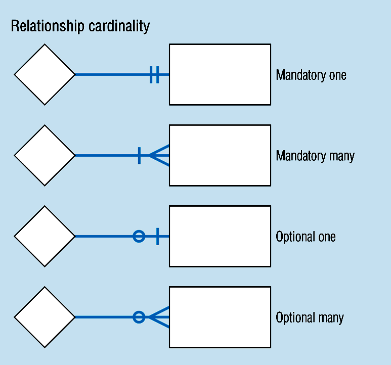
Classification of Relationships
1. Optional Relationships
- An entity may or may not be associated with another.
- Example:
- An Employee may or may not be assigned to a Department.
- A Patient may or may not be assigned to a Bed.
- Example:
2. Mandatory Relationships
- An entity must be associated with at least one other entity.
- Example:
- Every Course must be taught by at least one Teacher.
- Every Mother must have at least one Child.
- Example:
Types of Cardinality (Mapping)
| Type | Example | Description |
|---|---|---|
| One-to-One (1:1) | A Manager heads one Department and vice versa. | Each entity instance is related to exactly one in the other. |
| One-to-Many (1:N) | One Department has many Employees. | One entity relates to multiple instances of another. |
| Many-to-Many (M:N) | A Teacher teaches many Students, and a Student is taught by many Teachers. | Entities relate to multiple instances of each other. |
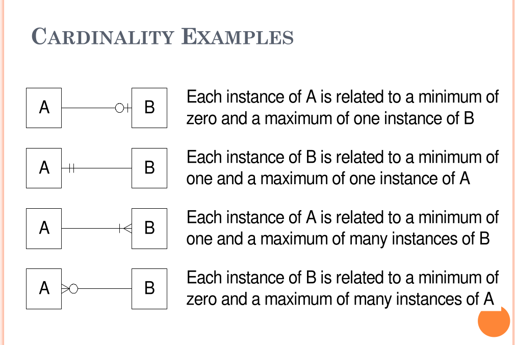
Cardinality Constraints
Cardinality defines the minimum and maximum number of relationships an entity can participate in.
Example:
- Each School may enroll zero or many Students.
- Each Student attends exactly one School.
Steps to Create an ERD
- Identify the entities.
- List each entity's attributes.
- Identify primary keys (PKs).
- Determine relationships between entities.
- Define cardinality for each relationship.
- Draw the ERD.
- Validate and refine the ERD.
Example: Company Scenario
Scenario Description
- A company has several departments, each with a supervisor and at least one employee.
- Employees belong to one or more departments.
- Employees work on one or more projects.
- A project must have at least one employee assigned.
Steps
1. Identify Entities
- Department
- Supervisor
- Employee
- Project
2. Find Relationships
- Department is assigned an Employee.
- Department is run by a Supervisor.
- Employee belongs to a Department.
- Employee works on a Project.
- Project uses Employees.
3. Draw Rough ERD
- Entities are rectangles.
- Relationships are diamonds connected with lines.
4. Define Cardinality
- Each Department has one Supervisor.
- Each Supervisor manages one Department.
- Each Department has one or more Employees.
- Each Employee may belong to multiple Departments.
- Each Project has one or more Employees.
- Each Employee can have zero or more Projects.
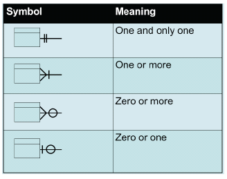
5. Define Cardinality Values
- One and only one
- One or more
- Zero or more
- Zero or one
Identifying and Mapping Attributes
Identify Attributes
- List essential properties for each entity:
- Department Name
- Employee Number, Employee Name
- Supervisor Name, Supervisor Number
- Project Number, Project Name
Map Attributes
- Assign each attribute to exactly one entity.
- Avoid duplicate attributes across entities.
Example
| Entity | Attributes |
|---|---|
| Employee | EmpNo, EmpName |
| Department | DeptNo, DeptName |
| Project | ProjNo, ProjName |
| Supervisor | SupNo, SupName |
Weak Entity Sets
Definition
A weak entity:
- Depends on another entity for its existence.
- Cannot be uniquely identified without a strong entity.
Examples
| Strong Entity | Weak Entity | Attributes |
|---|---|---|
| Patient | Treatment | TreatmentID, Description, Dates |
| Course | Module | ModuleNumber, ModuleName |
| Book | Chapter | ChapterNumber, ChapterTitle |
Notation
- Double Rectangle -> Weak Entity
- Double Diamond -> Weak Relationship
- Dashed Underline -> Discriminator attribute
Example
A Person entity has subtypes Employee and Customer identified by a discriminator attribute PersonType.
Example Exercises
Example 1 – Hospital System
Entities: Patient, Doctor, Test
Relationships:
- Doctor–Patient association
- Test–Patient link
- Doctor performs Tests
Attributes:
- Patient: Name, SSN, Insurance, Admission/Discharge Dates
- Doctor: Name, SSN, Specialization
- Test: TestID, Name, Date, Result, Time
Purpose: Organize patient data, ensure accountability, and maintain integrity.
Example 2 – Car Sales Company
Entities: Car, Customer, Employee, Invoice
Relationships:
- Employee sells Cars.
- Customer receives Invoices.
- Invoice belongs to Customer.
Attributes:
- Car: SerialNo, Model, Color, Year
- Customer: Name, Phone, Address, Location
- Employee: ID, Name, Address, Qualification
- Invoice: InvoiceNo, Date, Amount
Purpose: Manage sales efficiently and maintain relationships among staff, clients, and inventory.
Assignment Exercises
1. Car Accident Management System
Entities: Person, Car, Accident
Relationships:
- Person owns Car.
- Car participates in Accident.
- Person involved in Accident as Driver.
Attributes:
- Person: DriverID, Name, Address
- Car: LicenseNo, Model, Year
- Accident: ReportNo, Location, Date
2. Company Database System
Entities: Employee, Department, Project, Dependent
Relationships:
- Employee assigned to Department.
- Department managed by one Employee.
- Employees work on multiple Projects.
- Department controls Projects.
- Employees have Dependents.
Attributes include:
- Employee: SSN, Name, Address, Salary, Gender, Birthdate
- Department: DeptName, DeptNo, Location
- Project: ProjName, ProjNo, Location, HoursWorked
- Dependent: DepName, Gender, BirthDate, Relationship
Summary Table
| Concept | Description |
|---|---|
| Entity | Real-world object represented in the database |
| Attribute | Characteristic or property of an entity |
| Relationship | Association between two or more entities |
| Cardinality | Defines the numerical nature of a relationship |
| Weak Entity | Dependent entity identified through a strong one |
| ERD Purpose | Visualizes and structures the database logically |
| Key Deliverables | Entities, Attributes, Relationships, Cardinalities, ER Diagram |